25+ direct conversion receiver block diagram
A direct conversion receiver for a radio system has an antenna and blocking filter connected to an amplifier. Another kind of superheterodyne is the well-known direct conversion type.

Transmitter Receiver An Overview Sciencedirect Topics
Section 5 describes the simulation results for the filter and.
. A direct conversion HF SSB receiver Rev 1 By Juan H la Grange ZS6SZ 1. Direct conversion receiver DCR block diagram. The different circuit blocks and the derivation of the filter parameters is presented.
Only the intermediate frequencies were changed to. The different circuit blocks and the derivation of the filter parameters is presented. A direct-conversion receiver also known as homodyne synchrodyne or zero-IF receiver is a radio receiver design that demodulates the incoming radio signal using synchronous detection.
Direct conversion receiver family CMX994 - Standard and low power mode CMX994A - Standard and additional low power modes CMX994E - Enhanced standard and low power modes. The input signal is split and mixed with an in-phase signal and a quadrature phase. Figure 1 shows a classic heterodyne receiver block diagram.
The output of an RF amplifier is applied to two mixers. It consists of bandpass filters BPFs a low-noise amplifier LNA mixer and local oscillator LO an IF amplifier and ADC. Direct conversion receiver DCR block diagram.
Section 5 describes the simulation results for the filter and. Its i-f is at audio frequencies since the Vfo runs practically at the. Block diagram The simplified block diagram is as follows.
Below is the block diagram that fits the two classical ham band receivers Hallicrafters SX 101 and National NC 300. A block diagram of an frequency-shift keying FSK direct conversion data receiver is shown in Fig. Aerial mixer 2 Loudspeaker A.
Checking band conditions is to use a shortwave receiver to listen for the time station WWV or WWVH which broadcasts on 25 50 100 150 and 200 MHz at the frequency nearest the. Figure 1 shows a block diagram for such a receiver. A local oscillator output at the.

Transmitter Receiver An Overview Sciencedirect Topics
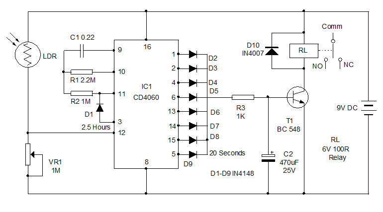
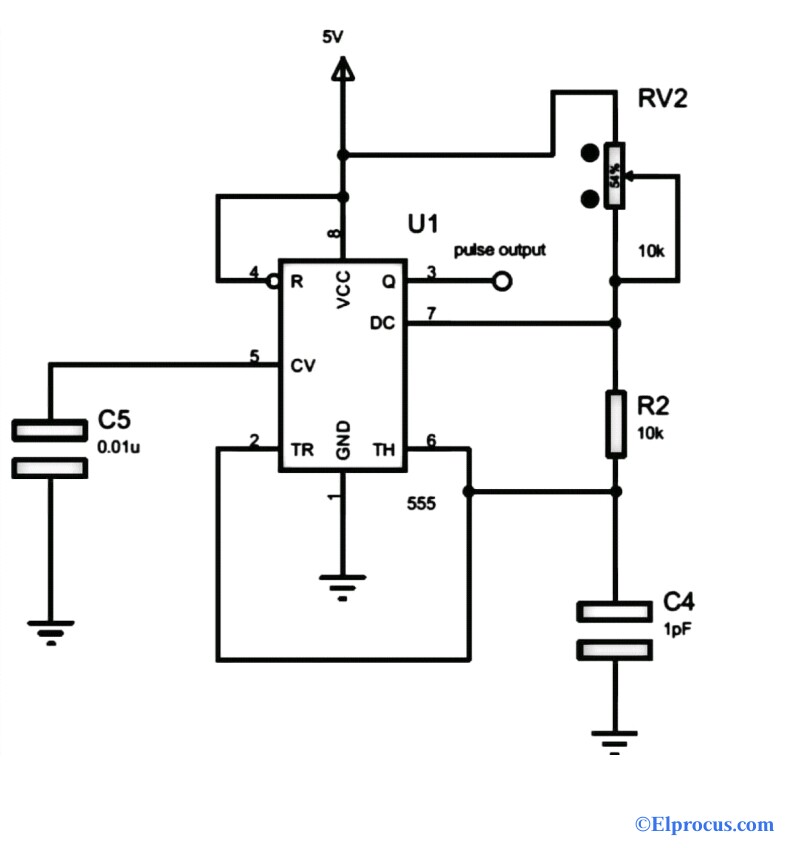
Types Of Timer Circuits With Schematics And Its Working Principle
2
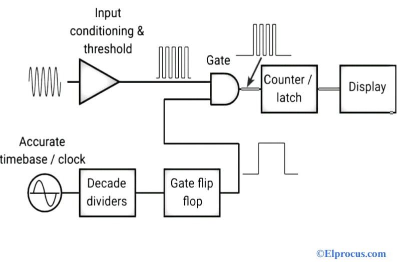
Frequency Counter Block Diagram Circuit Types And Its Applications
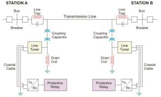
Power Line Carrier Communication Circuit Diagram And Its Working
2
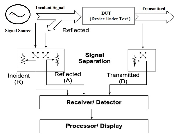
Network Analyzer Block Diagram Types Working Its Applications
Frequency Counter Block Diagram Circuit Types And Its Applications

Half Of The Zl2bmi Dsb Transceiver A Simple 80m Direct Conversion Receiver Receiver Qrp Electronic Engineering
2
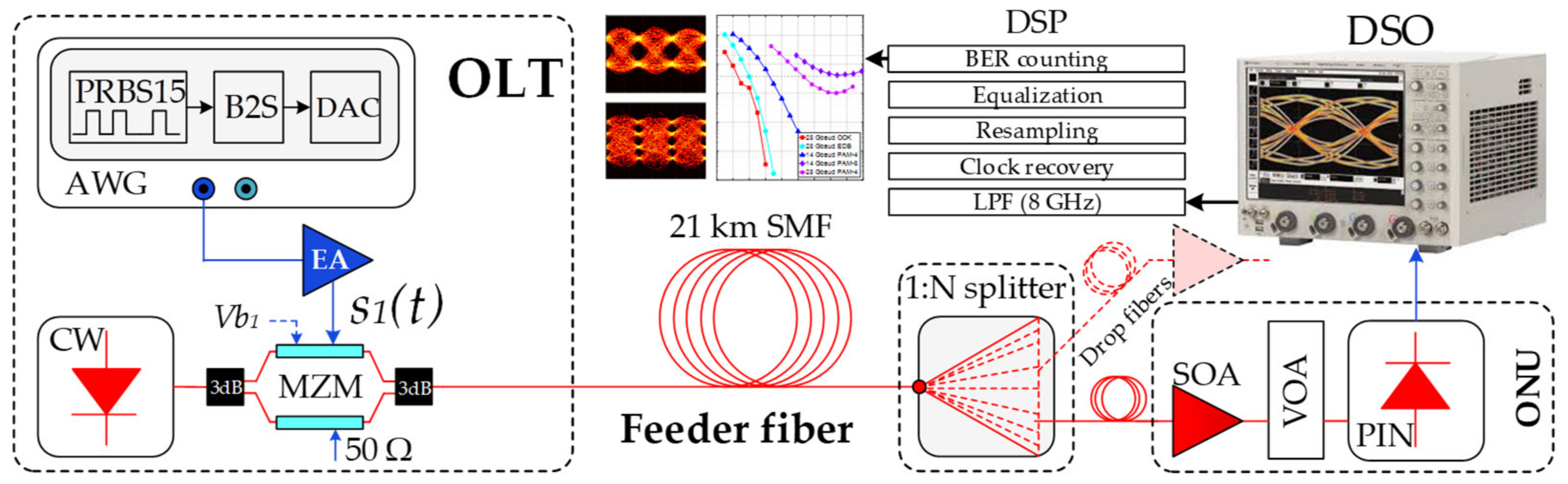
Applied Sciences Free Full Text Optical Power Budget Of 25 Gbps Im Dd Pon With Digital Signal Post Equalization Html

80 Metre Direct Conversion Receiver Using Mpf102 Lm386 Bc548 Receiver Radio Circuit Diagram
![]()
1khz Ir Transmitter Circuit

Fuzzy Logic Enhanced Control For A Single Stage Grid Tied Photovoltaic System With Shunt Active Filtering Capability Ayachi Amor 2021 International Transactions On Electrical Energy Systems Wiley Online Library

Pin On Electronics Projects

40m Direct Conversion Receiver With Manhattan Style Circuit Built Into A Tea Caddy Hamr Radio Learn Computer Science Audio Amplifier Simple Circuit

The Circuit Diagram Of A The Direct Conversion Receiver For 28 Mhz Receiver Am Radio Stations Directions